We use cookies to make your experience better. To comply with the new e-Privacy directive, we need to ask for your consent to set the cookies. Learn more.
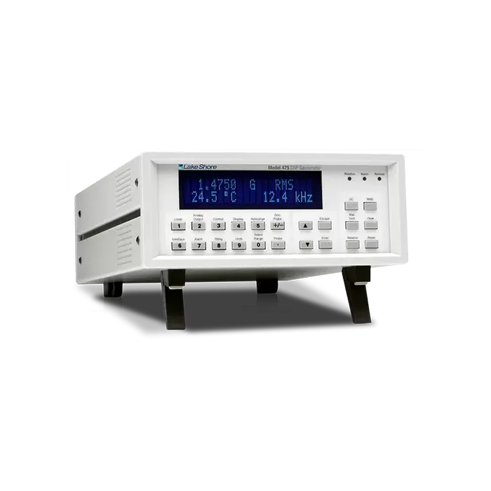
Model 475 DSP Gaussmeter
Model 475 features
- Full-scale ranges from 35 mG to 350 kG
- DC measurement resolution to 0.02 mG
- Basic DC accuracy of ±0.05%
- DC to 50 kHz frequency range (probe-dependent)
- 15 band-pass and 3 low-pass AC filters
- Peak capture to 20 µs pulse widths
- Data buffer sampling rates to 1000 rdg/s
- Computer interface sampling rates to 100 new rdg/s
- Integrated electromagnet field control algorithm
- Specialized and custom probes available
The first commercial digital signal processor (DSP) based Hall effect gaussmeter, the Model 475 provides accurate, stable, and repeatable field measurement while simultaneously offering an unequaled set of useful measurement features. The Model 475 is intended for demanding DC and AC applications, and in many cases, it provides the functionality of two or more instruments in a field measurement system.
The power of DSP technology is demonstrated in the superior performance of the Model 475 in DC, RMS, and Peak measurement modes.
Field control
A built-in PI control algorithm turns the Model 475 into an essential building block for magnetic field control in electromagnet systems. It, along with a voltage-programmable magnet power supply, is all that is needed to control stable magnetic fields in an electromagnet at the user-specified setpoint. One of the built-in analog voltage outputs drives the program input of the power supply for either bipolar or unipolar operation.
High-speed data transfer
The IEEE-488 interface can be set to send readings in binary format rather than the more common ASCII format. This reduces interface overhead, enabling real-time reading rates up to 100 new readings per second. Temperature compensation is not available at the highest interface rate.
Data buffer
Internal memory provides storage for 1,024 field readings in a data buffer. The buffer can be filled at high speed, up to 1,000 readings per second, which is as much as ten times faster than the computer interface. Stored readings can then be retrieved over interface at slower speed and processed offline. A trigger input can be used to initiate the data log sequence. Slower sample rates can be programmed if desired.
Trigger in and trigger out
A TTL-level hardware trigger into the instrument can be used to initiate the data log sequence. A TTL-level hardware trigger out indicates when the instrument completes a reading and can be used to synchronize other instruments in the system. An IEEE-488 software-based trigger can be used like the hardware trigger in.
For more information about the instrument, including specifications and currently available Hall probes and sensors, visit the product page on the Lake Shore website.
